Projects
As an Elektronik Ingénieur-ish had the pleasure of completing or half way there side projects and actual deliverable projects. They are listed in reverse chronological order.
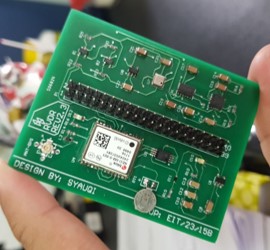
H-Bridge with Teensy 4.0
Associated with - University College London


An H-bridge control with a Teensy 4.0. In this project, our research group is planning to supply a 100 kHz–500 kHz, 100 V–600 V / 2 mA AC voltage to actuate a material called Liquid Crystal Elastomers (LCE).
We are using the Teensy 4.0 due to its clock speed of 600 MHz, which gives us real-time control for our PWM signal. With its FlexPWM, we can generate PWM signals on two channels sharing the same timer. The second channel’s PWM can complement the first PWM channel, making it suitable for driving an H-bridge.
Since the H-bridge runs at hundreds of volts, we use a gate isolator to drive the MOSFETs, specifically the Texas Instruments UCC21520. Our high-voltage supply comes from the FS60P-12 from XP Power. It is capable of supplying 0–6000 V by controlling the input voltage from 0–12 V (linear control). We control it with a power op-amp in a non-inverting configuration with a gain of 2.8. So a 3.3 V signal from the Teensy GPIO would give us 9.24 V, which translates to 4,620 V of HVDC output.
To vary the voltage going into the op-amp, we use PWM by controlling its duty cycle with a two-stage low-pass filter to smooth out the square wave into DC.
Our MOSFETs are GaN FETs rated at 650 V / 55 A. I don’t really know why I chose them in the first place, tbh. A SiC MOSFET would have sufficed—well, at least I’m not the one who’s paying for them, at £7.58 per MOSFET!
Down the line, the project will be extended to become an Electrical Impedance Tomography (EIT) system using high voltage rather than low voltage. We plan to map the electrical conductivity of the LCE. This would give me a brain hemorrhage trying to figure out the high‑speed switching in high voltage.
update - 30/07/36

Built the circuit and… I got the MOSFET pin wrong 🤦♂️. I don’t know what’s going through my big brain—I used a SPICE model as a symbol and thought that all 3-legged MOSFETs have the same pinout assignment. Turns out every manufacturer does things differently. What an idea…

To top that, I had to replace all the MOSFETs and the h-bride driver when I tested it more than 100V. Since the supply voltage is load dependent, I supecting that it may jump all the way to >2kV for a brief moment.
The way the High Voltage DC converter FS60P-12 work is a linear control output. The input of the converter is 0-12V and outputting 0-6kV with 1.67mA.
During the testing we only supply from 1V to 5V. Around 1V we are getting about 100V output due to our load is not that high in resistance. By using basic Ohm’s law, looks like the load that to be expected is around Mega Ohm for it to output the expected voltage of 500V (the current ouput vary).
\[V = I \cdot R\] \[R = {6kV \over 1.67mA}\] \[R = 3.59M \Omega\]Now our load, LCE is only around 50k Ohm in initial state and only decrease from there onwards when it start to heat up and curl. What I am thinking (no idea if my assumtion is true or not) is that during the tranisition period from on to off state the resistance spike from mili Ohm to Giga Ohm. The brief spike during the transition prolly increase the voltage to kilo volt when tested with 5V input (assunming it linear, 2.5kV output for a brief momment).
Pico Peltier TEC controller
Associated with - University College London
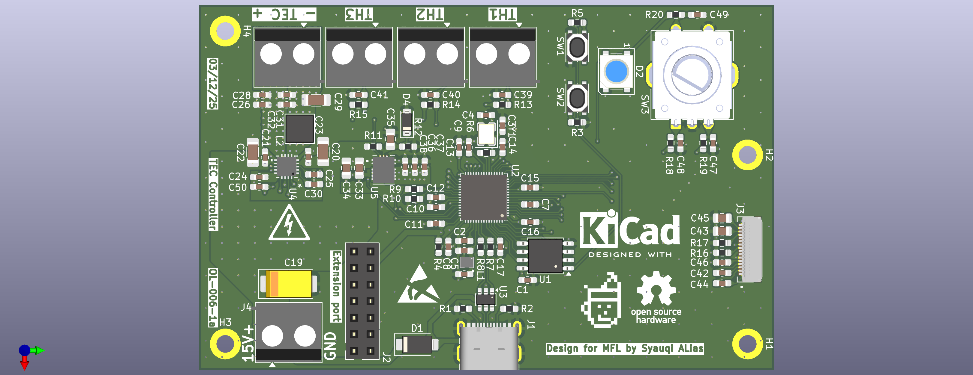
A Peltier module controller designed around Raspberry Pi RP2350 and Analog Devices LT8722 Half-bridge Driver supplying 15V at 4A max PWM with an LC low-pass filter. This thingamajig will be placed inside an Atomic Force Microscopy to cool samples down until condensation forms on the surface.
Hardware Features:
- Sensing: three temperature probes monitoring the cold side, hot side, and ambient room temperature.
- Interface: a 128×64 OLED panel for data visualization and a rotary encoder with a push-button for setting target temperatures.
- Status: addressable RGB LEDs for system status indication.
- Expansion: a dedicated port for future upgrades, such as PWM fan control.
Design Constraints: To minimize vibration interference with the sensitive AFM cantilever, the system currently relies on passive cooling via a heat-sink on the hot side. However, the expansion port ensures that active cooling can be integrated later if needed, we’ll see how it goes.
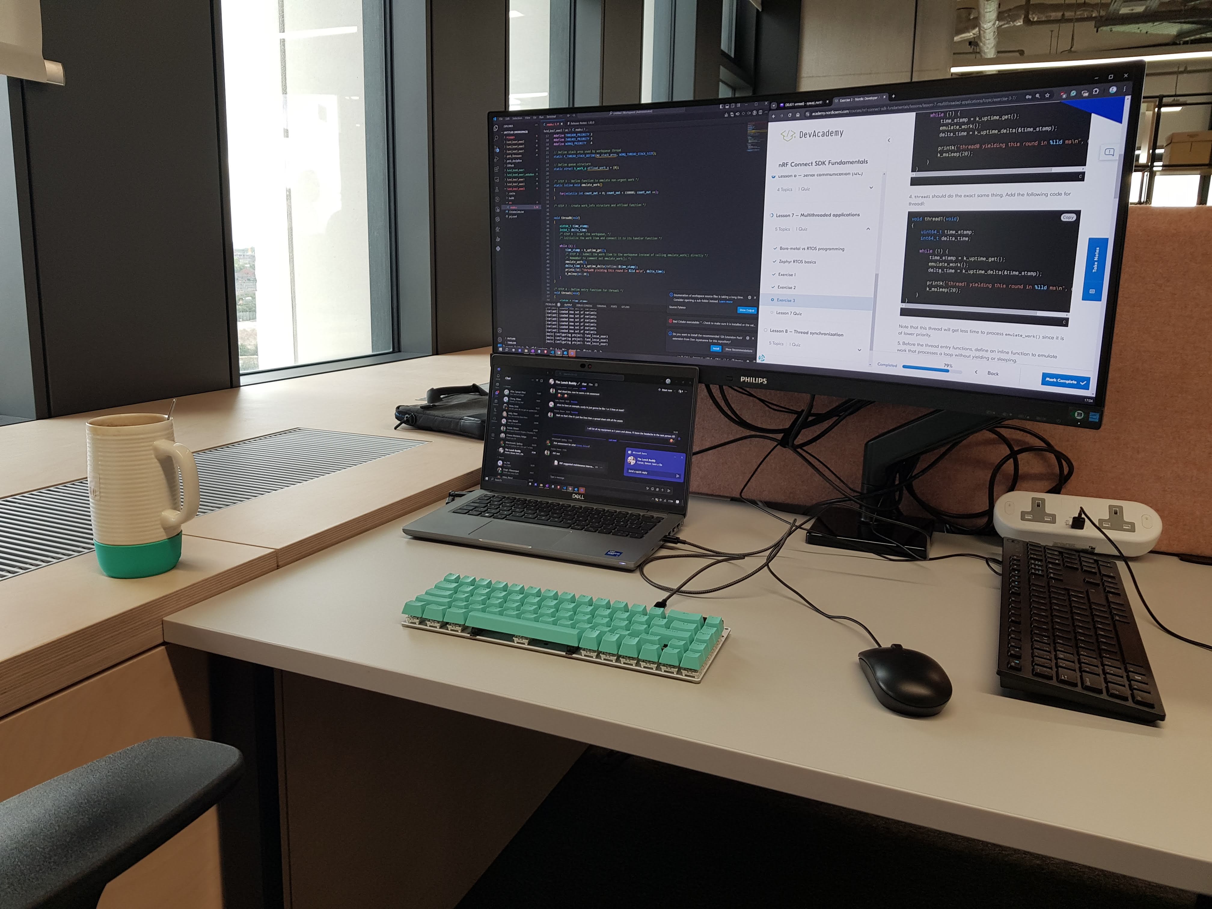
Software Architecture: The system utilizes a PID control loop for temperature regulation. Leveraging the RP2350’s dual-core architecture, I dedicated one core to the Peltier control loop and the second core to the OLED display to make sure display timing does not interfere with process control. The firmware is implemented using Zephyr RTOS, my very first RTOS project since doing those Zephyr courses online, better put it to use yo!
Partly written by AI, if not, I’ll be yapping with a lot of unnecessary information ¯\_(ツ)_/¯. The future is now, old man.
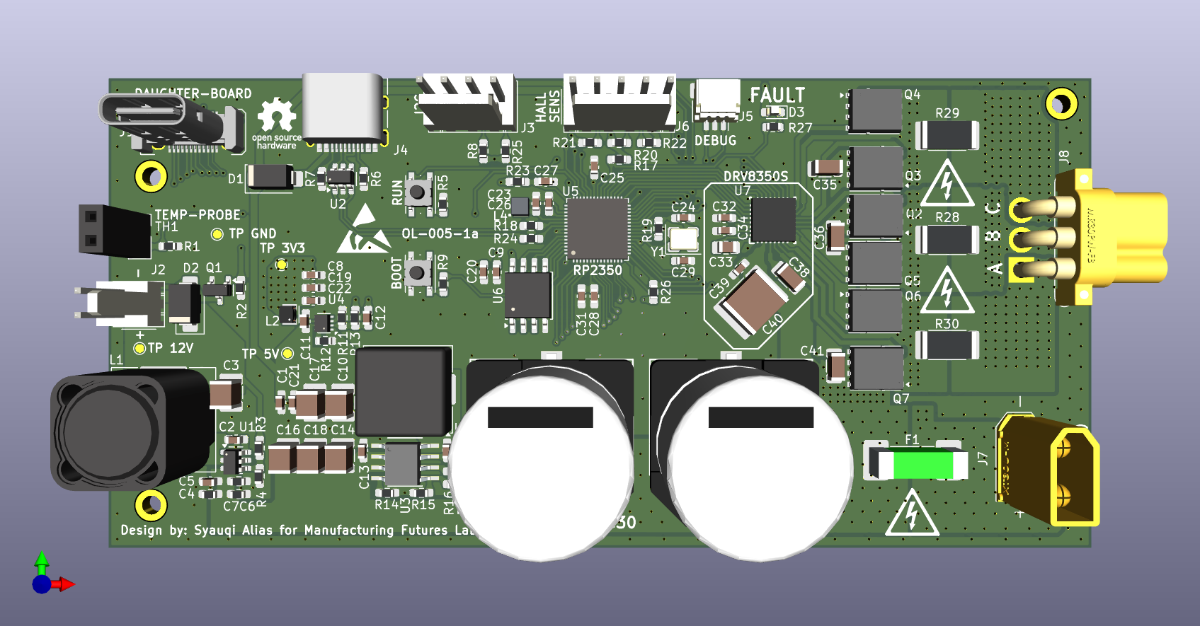
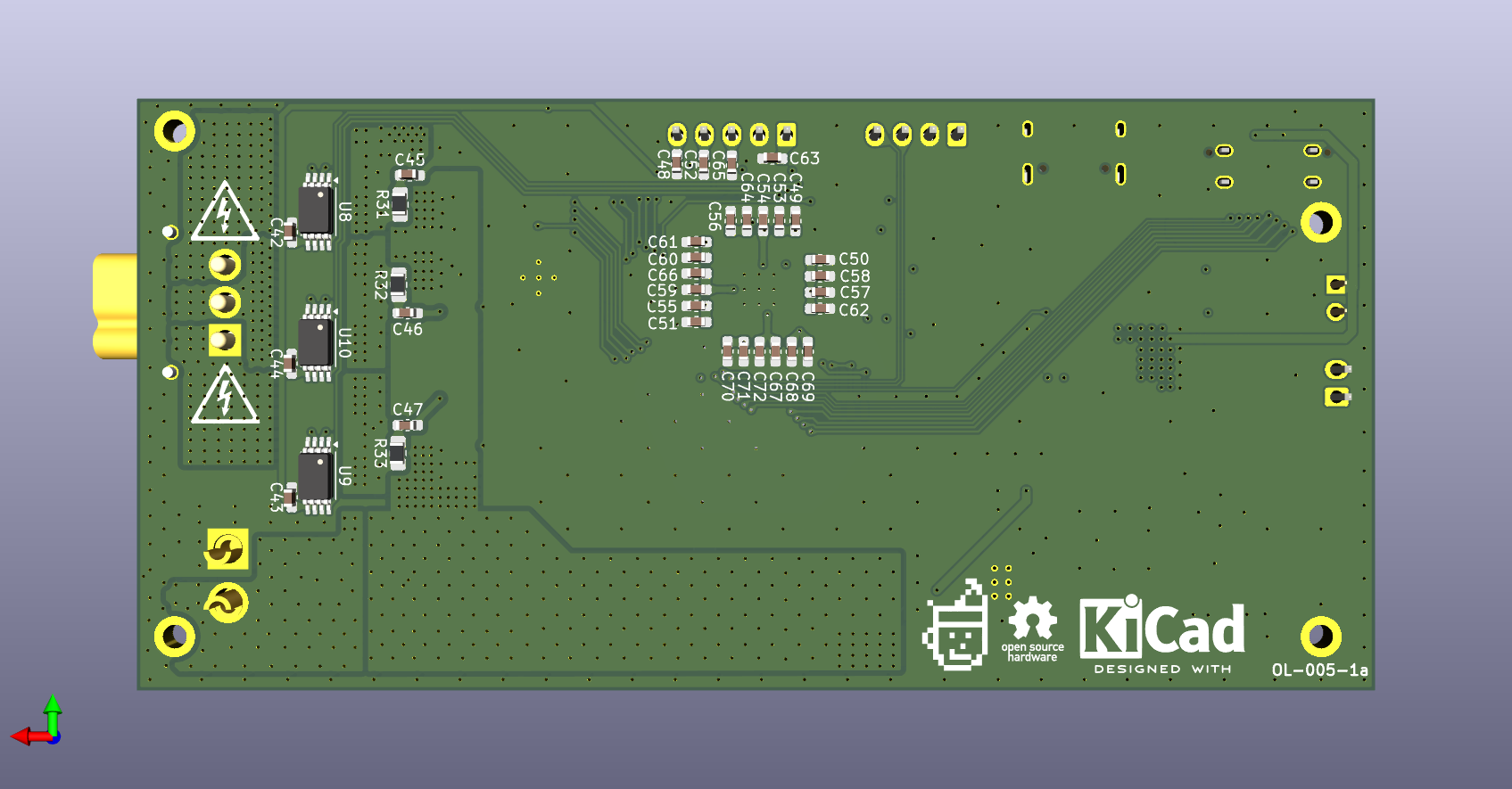
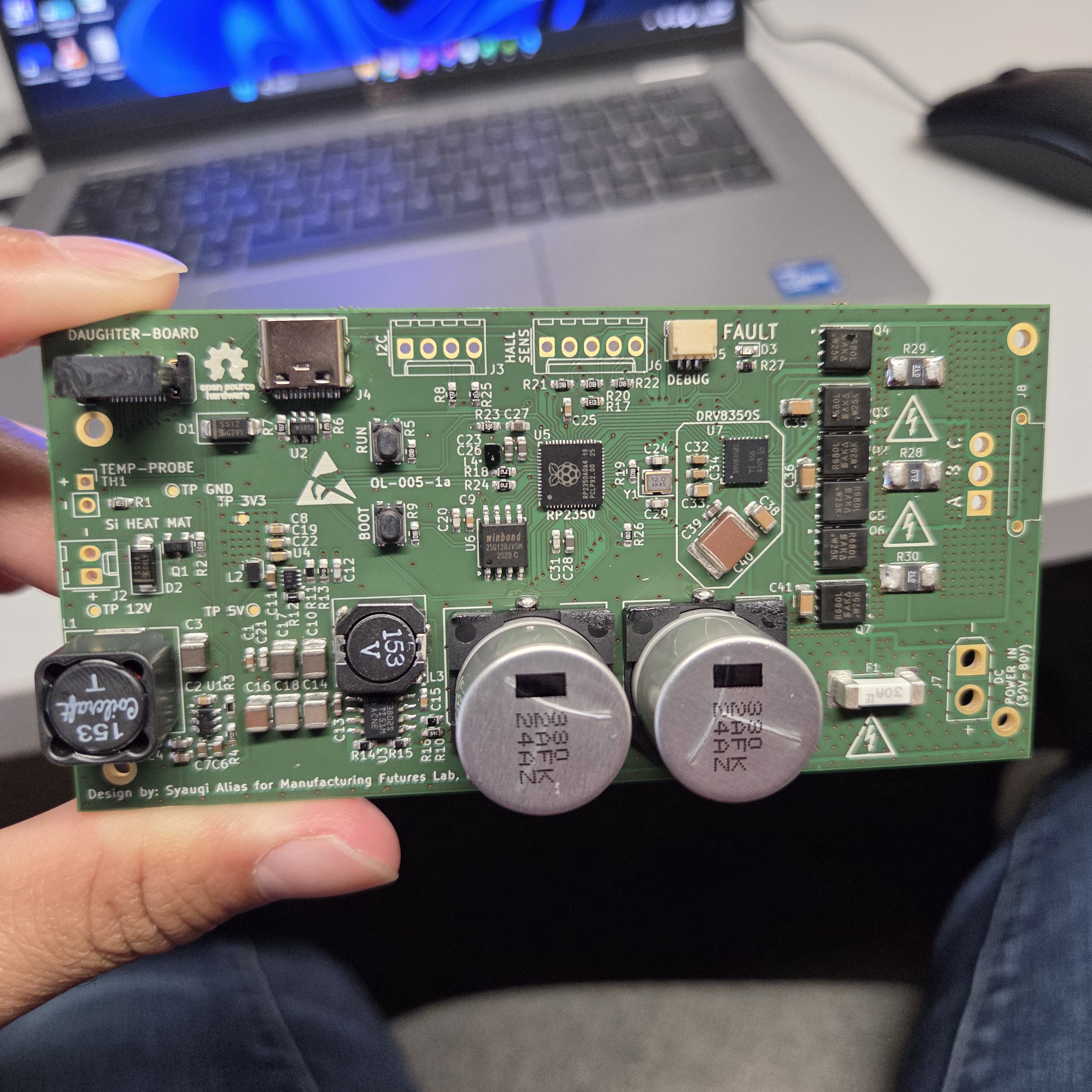
Pico-BLDC-Controller
Associated with - University College London
I’m designing a custom hotplate magnetic stirrer to integrate into our lab’s Opentrons robot at the Manufacturing Future Lab, University College London.
As this is my first time designing motor control systems, specifically for a BLDC motor, I’m using a half-bridge configuration to control the three-phase input.
I am quite nervous designing anything that handles more than 5V. The motor we have in the lab is a 260W 30V/7A Maxon motor.
I’m using a Raspberry Pi microcontroller, specifically the new RP2350 dual-core model running at 150 MHz, because its design is much simpler than that of an STM32 MCU. I’ve come across many discussions claiming the RP2350 is not ideal for controlling BLDC motors, particularly when reading the current output. It’s considered “slow” in converting ADC values compared to the STM32. However, I plan to open-source the design entirely, and I hope someone with more expertise can use it to develop firmware that addresses this issue.
For the pre-driver, I’ve chosen the Texas Instruments DRV8350S. This IC significantly reduces the component count and complexity of the design. I won’t need to implement filtering, snubbers, or anything like that—just the pre-driver and the MOSFET gate. Mah brain is not build for complicated things (XuX)
On the software side, I’m implementing the SimpleFOC library to save development time. Maybe if the motor runs well, I’ll create the firmware from scratch?
The schematic is complete-ish. I have sent it to multiple colleagues and online forums for feedback. I spent a lot of time going back and forth on my component choices, but it was a great learning process. I’ll post updates along the way.
You can download my schematic by clicking this link: Download PDF.
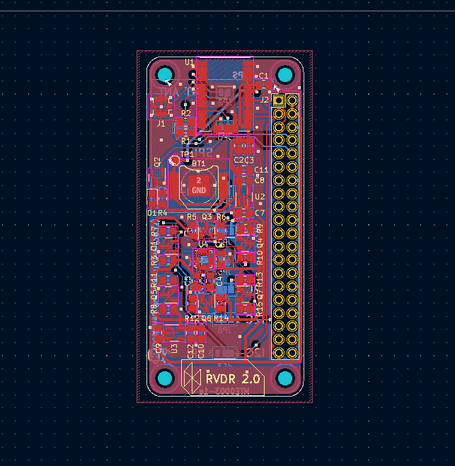
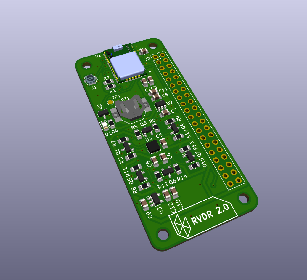
RVDR V2.0
Completed in 2023 - not to be confused with RVDR+
This is the second revision of the Road Vehicle Data Recorder (RVDR). It’s a smaller version of the original with a few key changes:
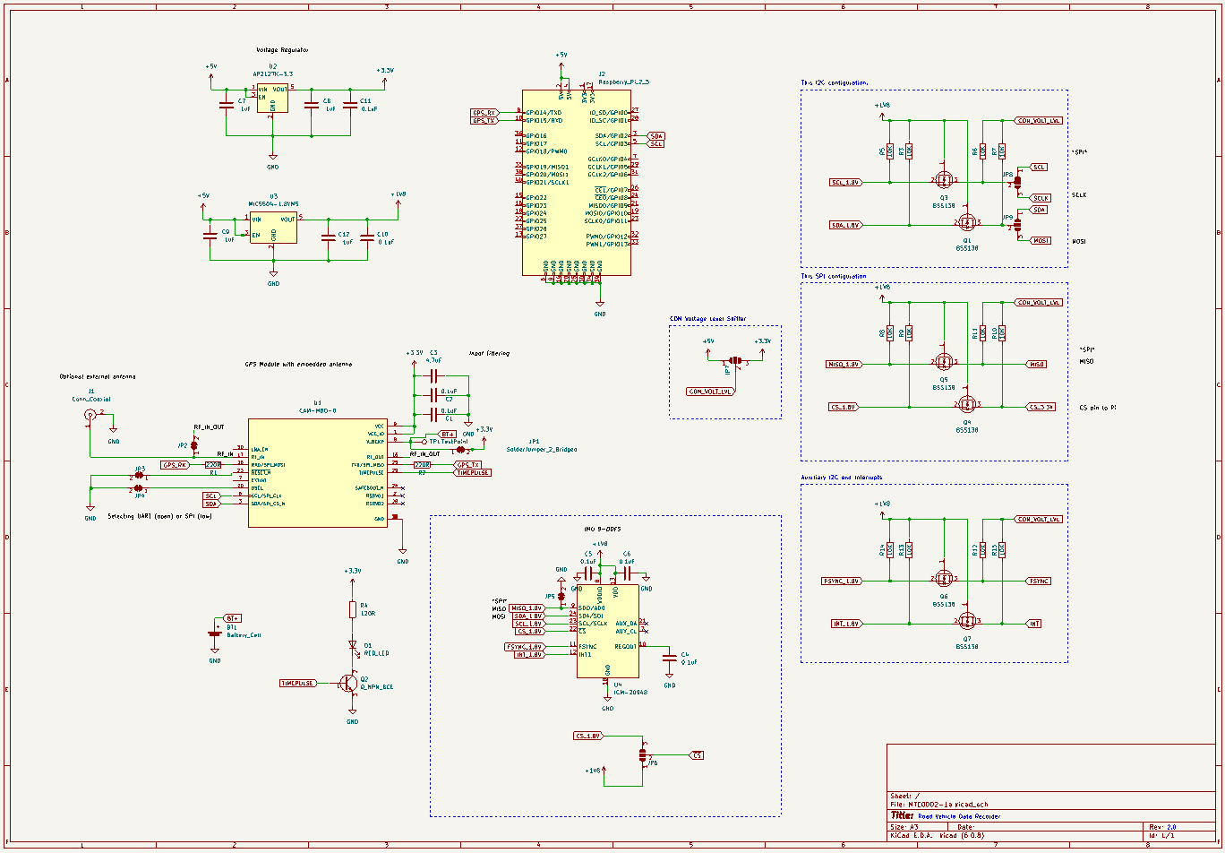
- Replaced the GNSS module with a u-blox CAM-M8 series module that has a built-in antenna (an external antenna is optional).
- Replaced multiple sensor ICs with a single TDK ICM-20948 9-Axis MEMS motion tracker (though this is technically a downgrade from the previous 10-DOF sensor).
- Reduced the size to match that of a Raspberry Pi Zero W.
- Added an option on the back of the board to select the communication protocol: UART, SPI, or I2C.
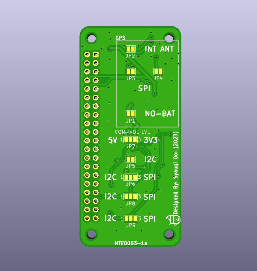
TIP
There are a few things I can do to improve the design, like implementing a single voltage shifter IC (e.g., Analog Devices MAX3378EE) rather than using multiple MOSFETs for level-shifting. This would free up space for more sensors. Perhaps this is something I could explore in the third revision.
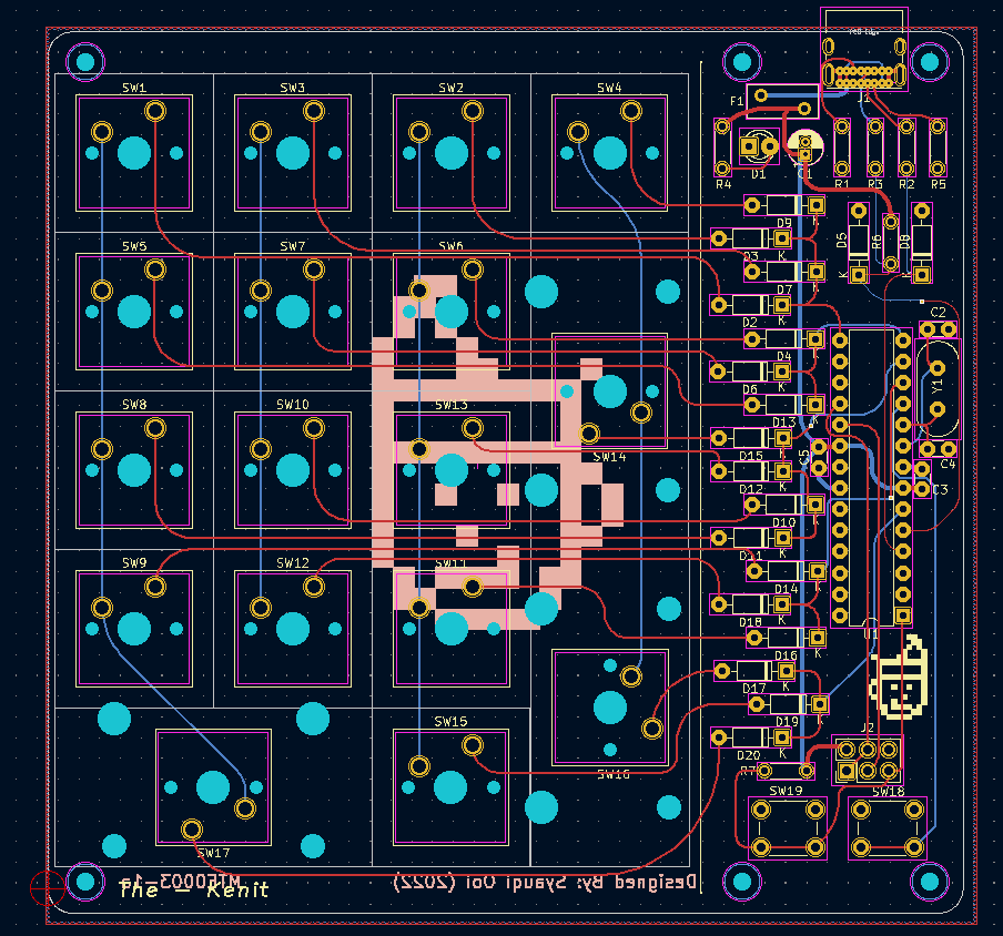
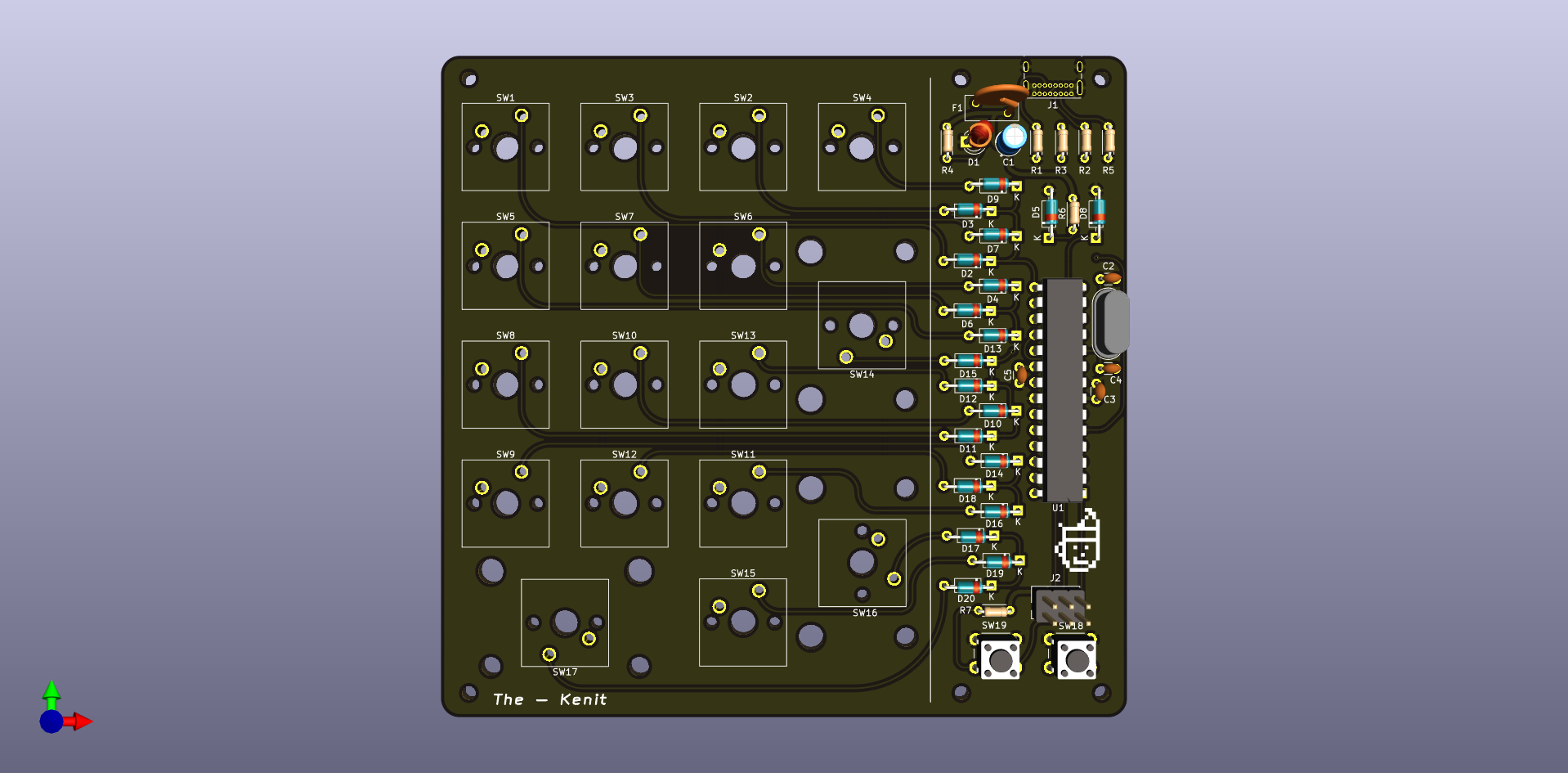
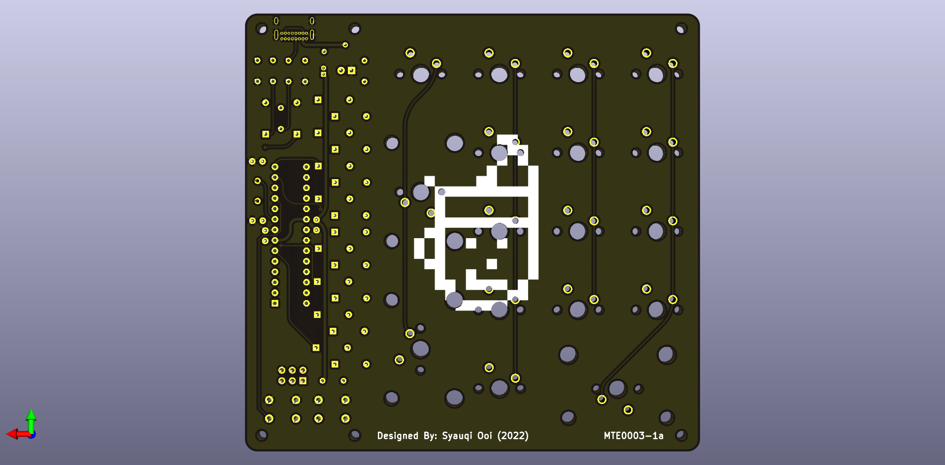
The Kenit Numpad
Meet “The Kenit” Numpad (I ran out of ideas for what to name it). This time, I experimented with the KiCad “Rounded Tracks” plugin. Does it have any practical benefit? Probably not, but does it look cool? Definitely!
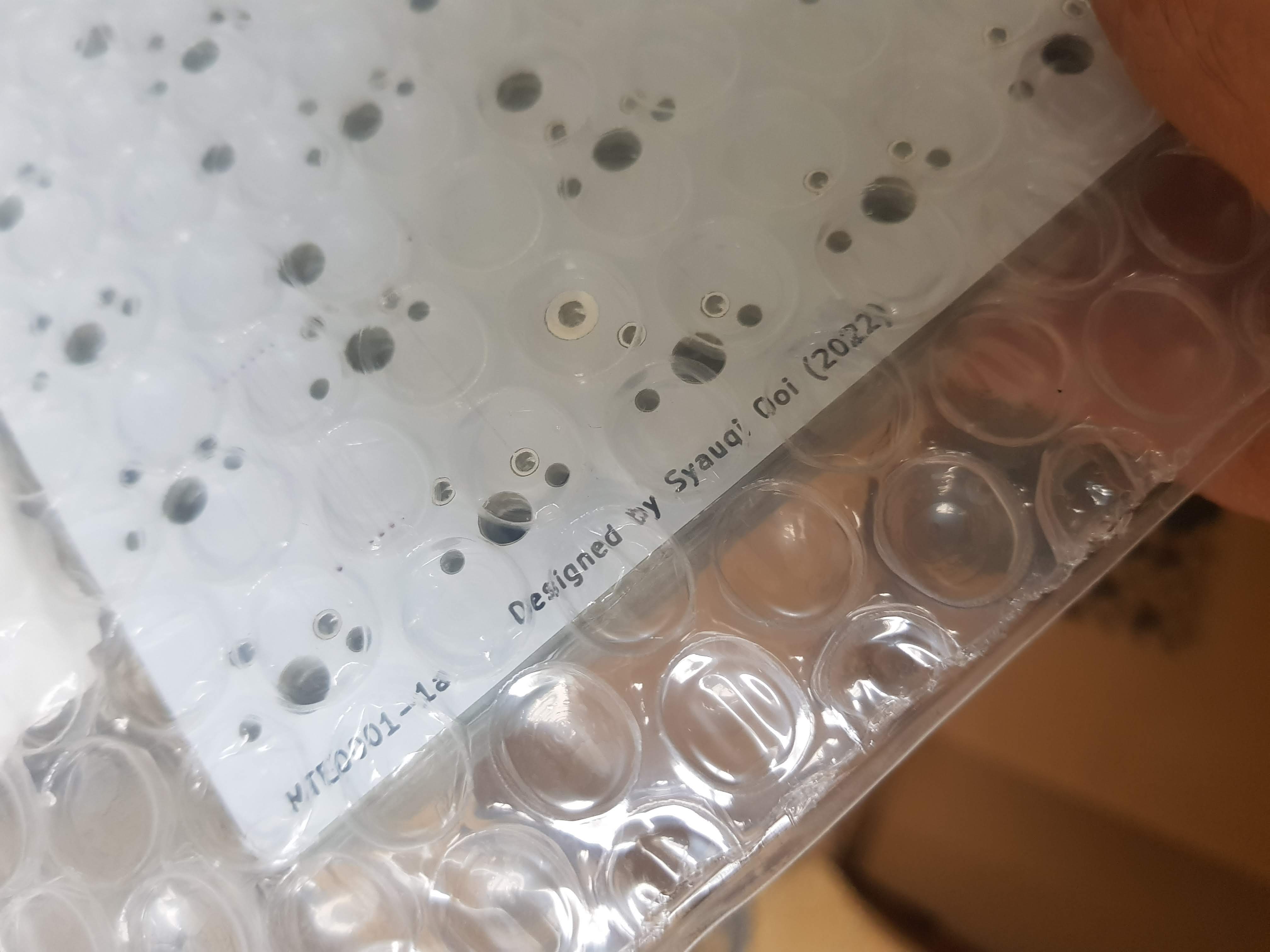
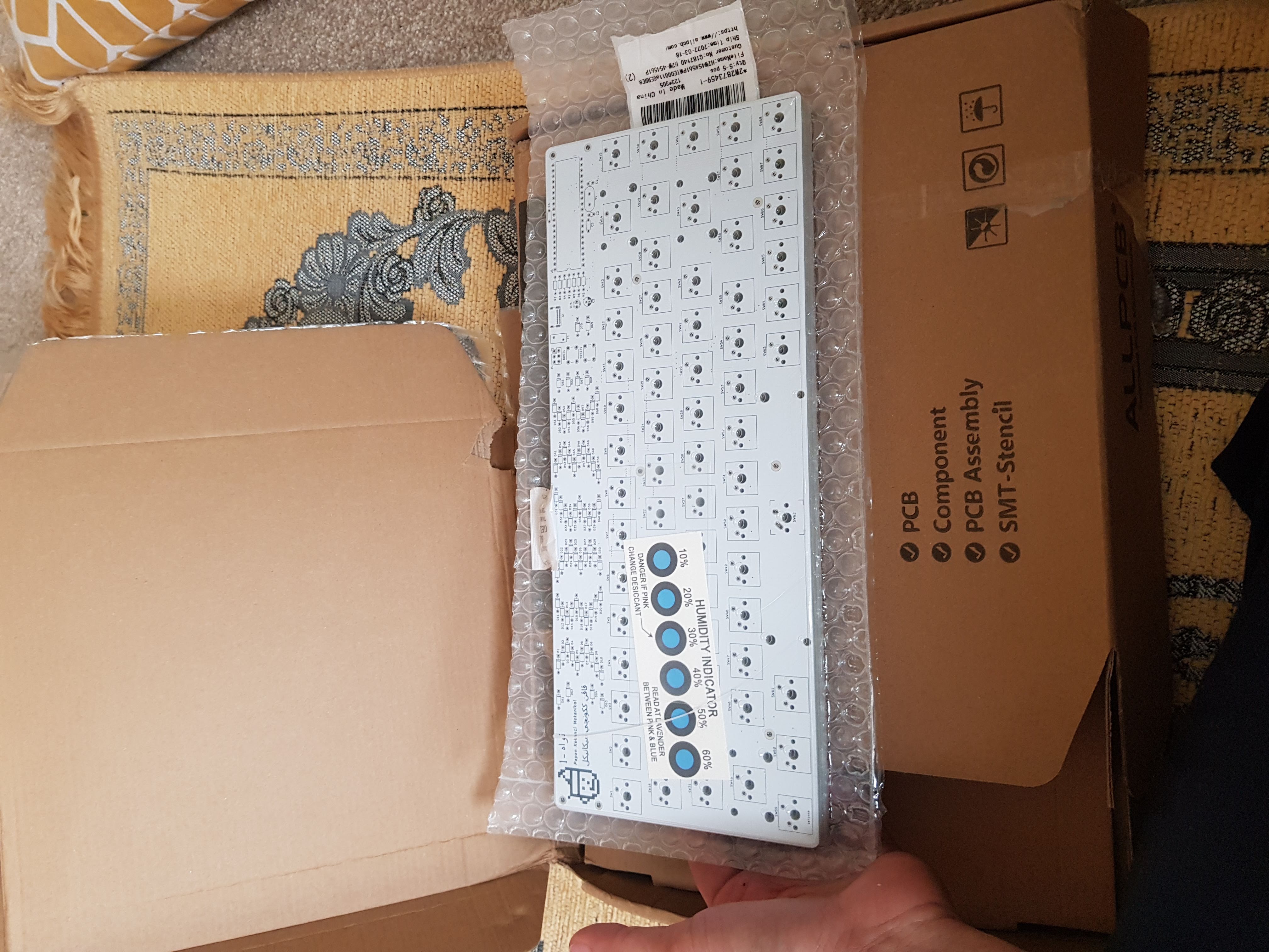
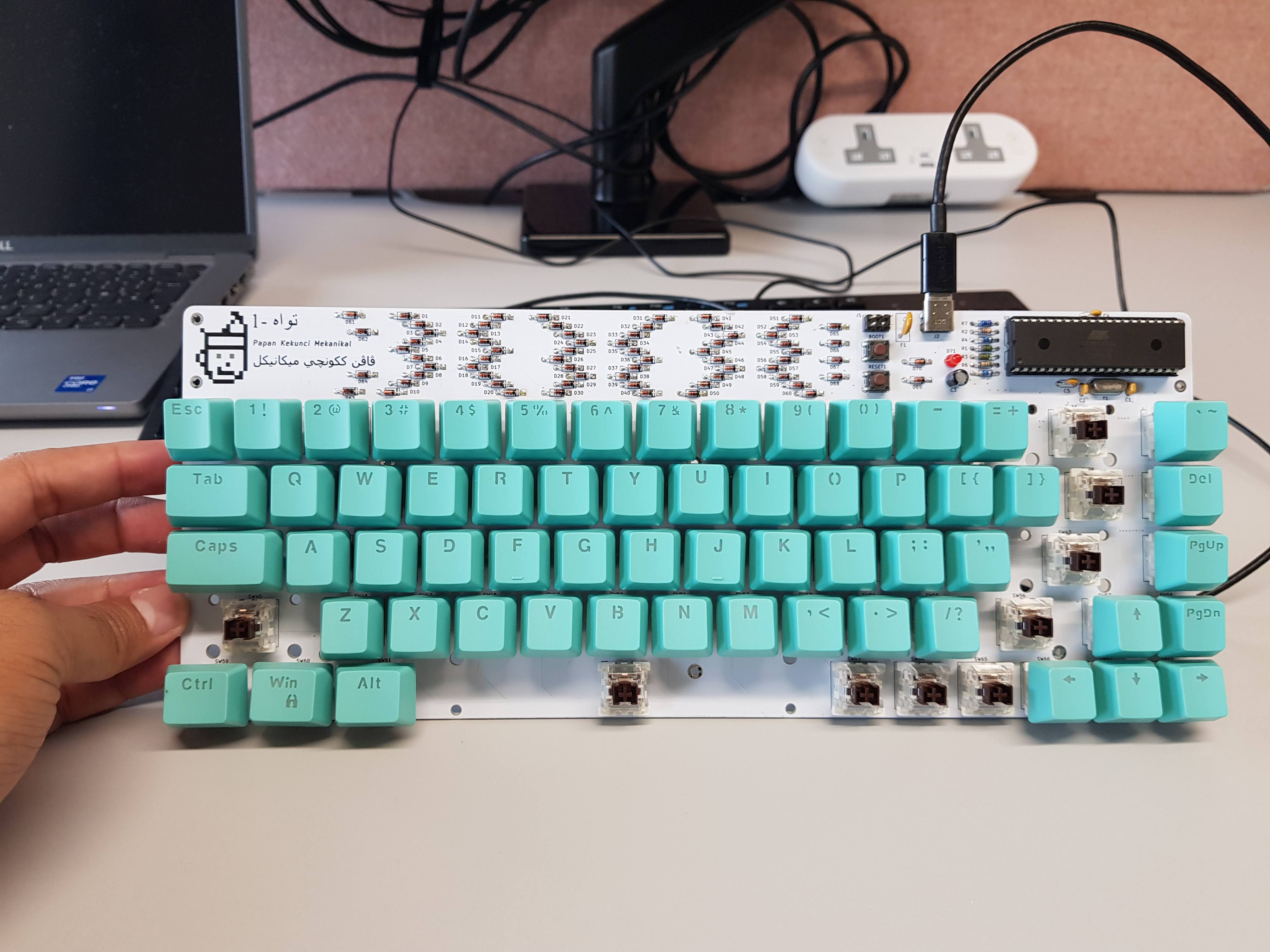
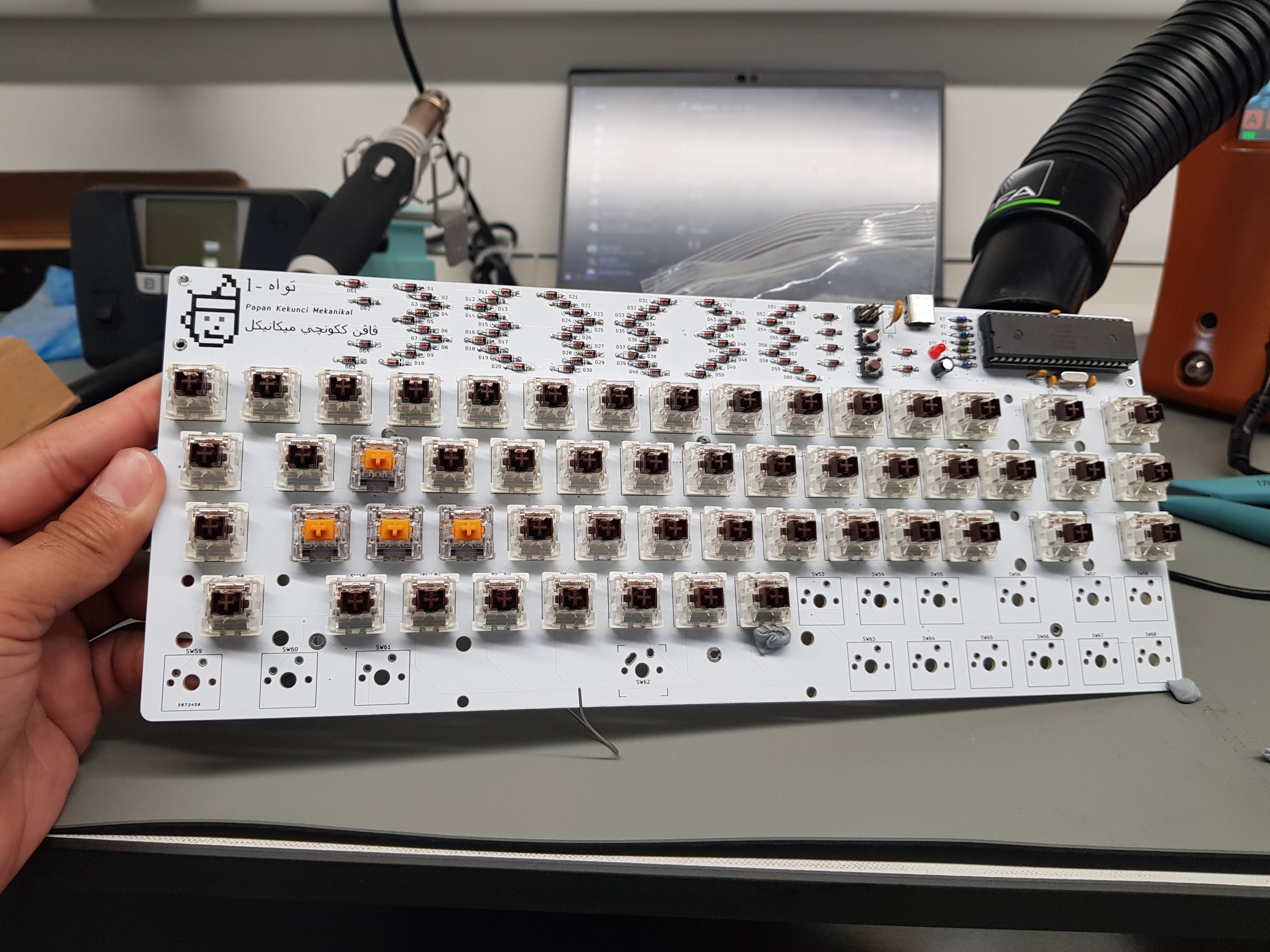
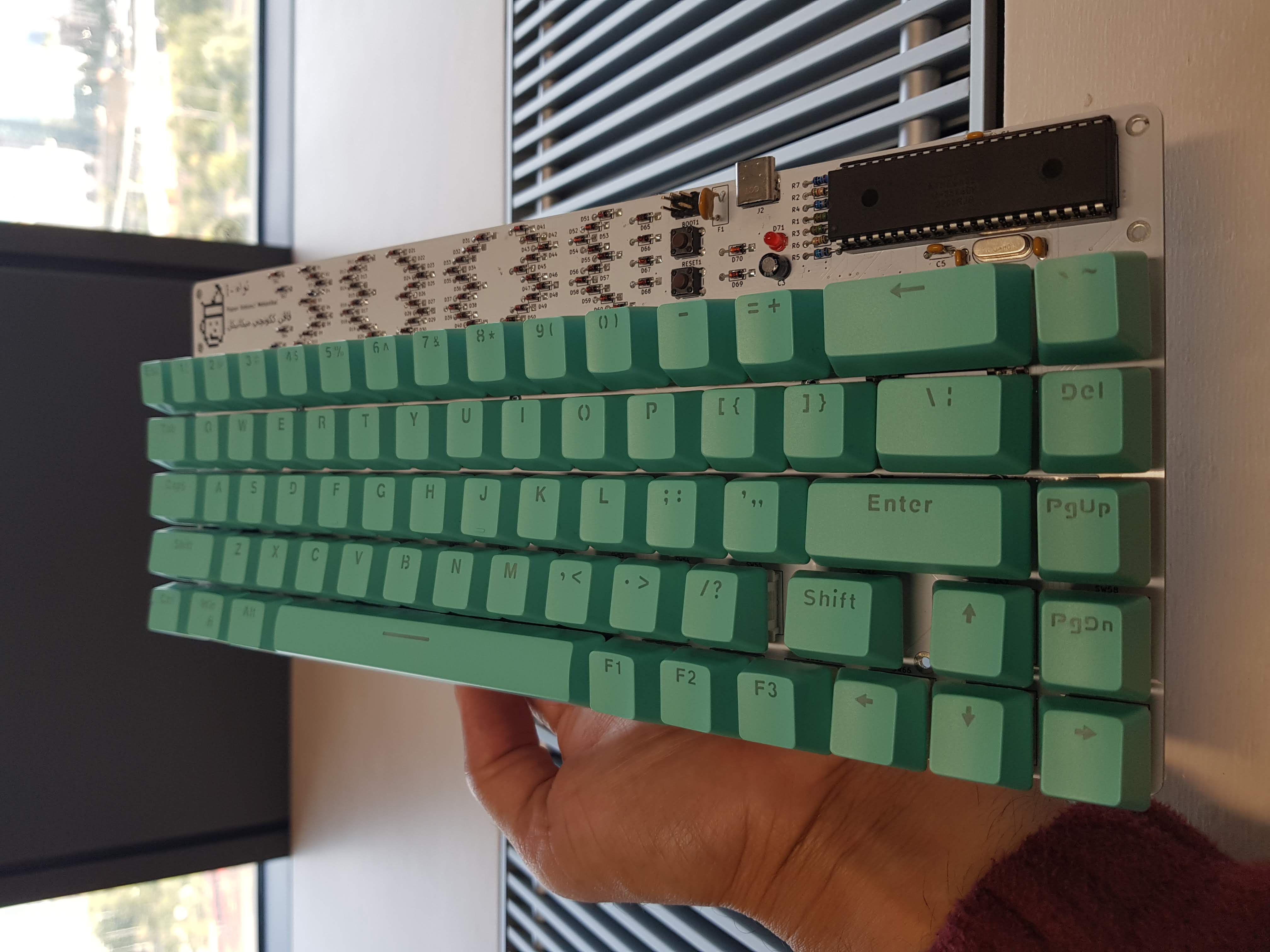
1-تواه/Tuah-One
1-تواه/Tuah-One! A custom 75% mechanical keyboard project based on an open-source schematic. After months of design, it was put into production in April this year. And… that’s it. The chip shortage and the high cost of producing a small quantity made it very, very expensive.
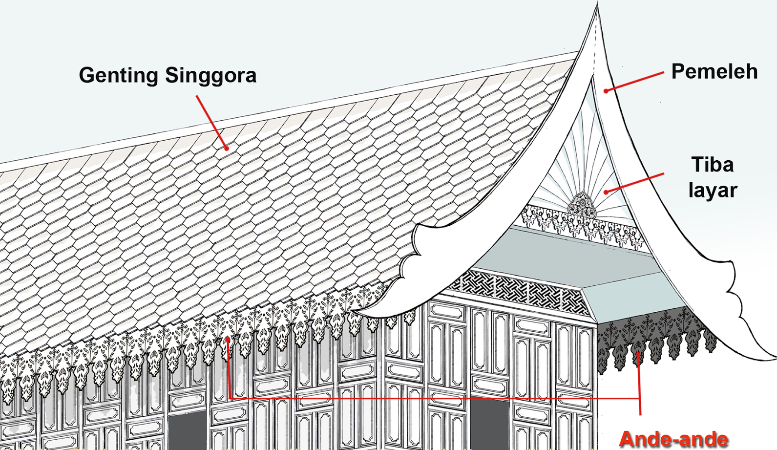
I tried to arrange the diode array in a manner that resembles traditional Malay carving (ukiran tradisional Melayu)—a repeated shape with slight differences in a repeating arrangement. It may not look like much, but I tried.
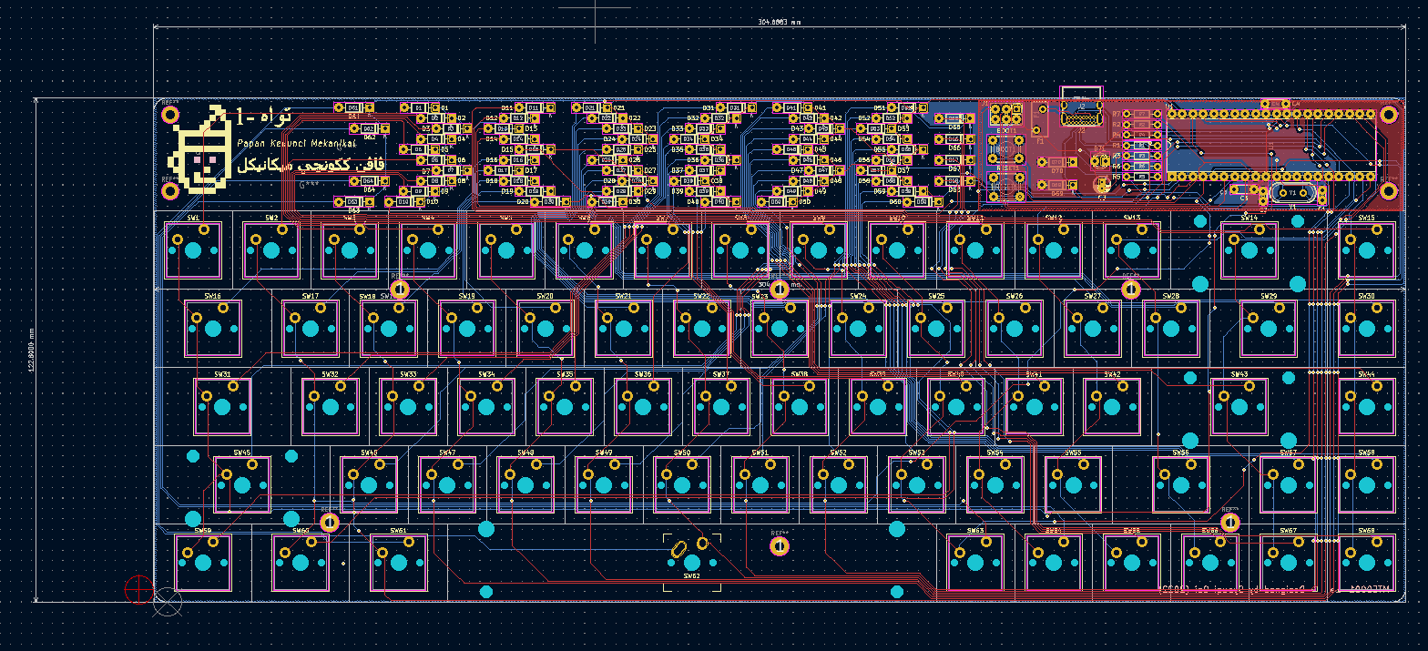
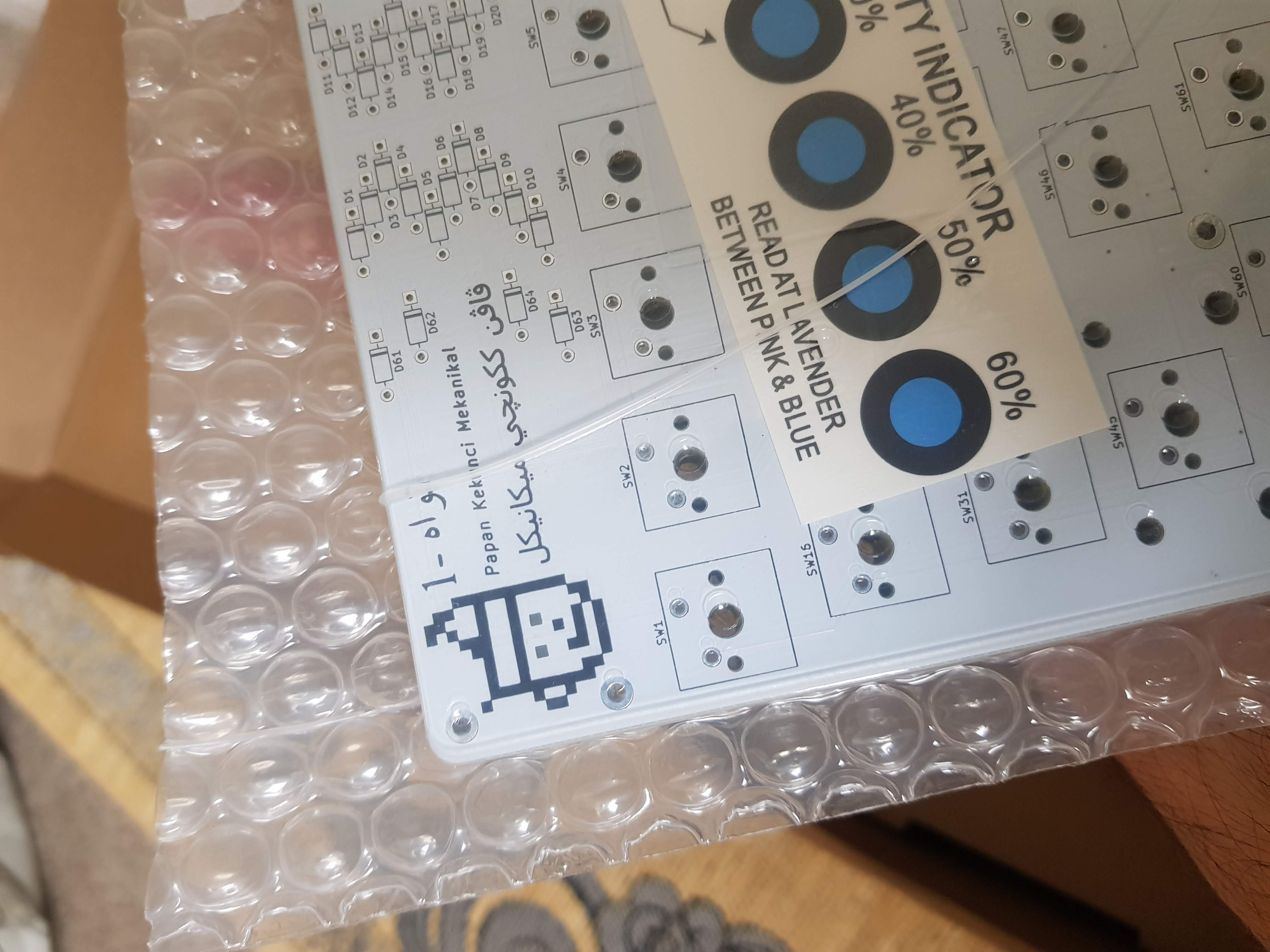
“1-تواه/Tuah-one” means “lucky one”—well, not exactly. A quick Google Translate shows “tuah” is “good luck,” written in Jawi (the Malay alphabet system before the Latin alphabet was introduced). It’s paired with pixelated art of “Hang Tuah,” a Laksamana (Admiral) in 15th-century Melaka, considered by Malays to be one of history’s greatest silat masters. Hang Tuah is wearing a traditional Malay headgear called “Tengkolok” or “Tanjak,” hence the triangular look (I tried :P).

Update - 21/06/2025
After 3 years of planning, designing, fabricating, assembling, testing, and a sprinkle of procrastination, here it is: Tuah-one/1-تواه! My attempt at an “Ukiran Melayu” inspired design.
Now the keyboard sits inside my office closet (10 months and counting) and never sees the sunlight. [insert sad violin music]
TIP
One last thing… I’m selling this. Seriously. If any buyers or companies want to license my design, I’m open to talk. 😂
Individual Project Dissertation
Associated with - The University of Manchester
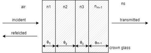
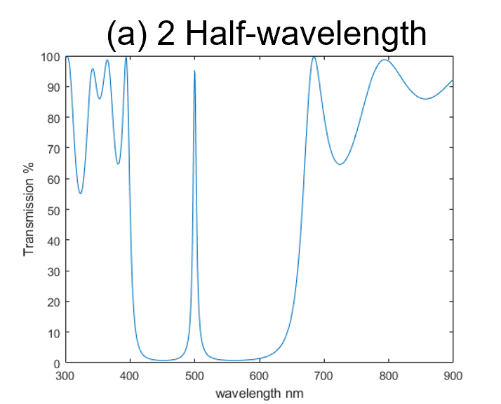
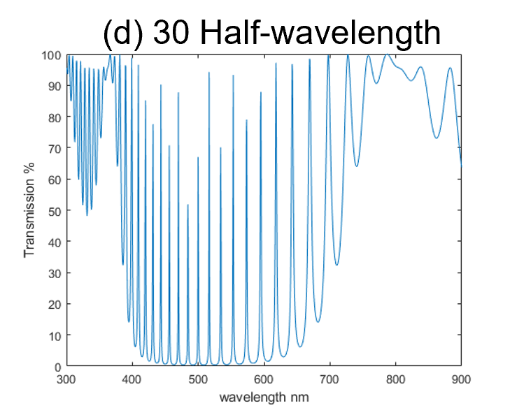
Design and Application of a Tuneable Optical Filter for High-Speed Optical Communication Systems (MATLAB)
I designed the arrangement of passive optical filters (Fibre Bragg gratings) in an optical fiber for a high-speed communication system. I then simulated it with different wavelength bands to obtain over 95% transmission. This experiment focused on the near-infrared (800nm+) and visible light (400-700nm) spectrums.
Embedded Systems Project
Associated with - The University of Manchester
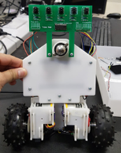
I led software development for a buggy capable of autonomously following a line using reflective optical sensors. We approached the problem systematically by prioritizing simpler tasks first.
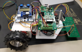
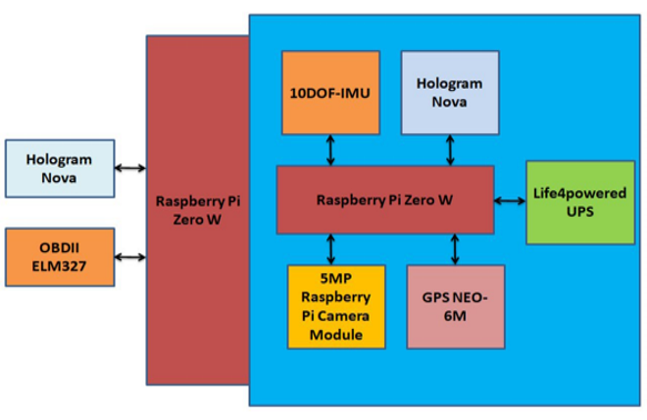
RVDR V1.0
Associated with - German-Malaysian Institute
I led software and PCB development for a “black box” device for a logistics fleet. The device consists of a camera module, GPS (GNSS), an IMU sensor, and an OBD-II reader to send live data to an MQTT client (Losant IoT) for real-time data visualization.
Java Programming - Multithreading Operation
Associated with - German-Malaysian Institute
Coursework: Build an Alarm Clock
I modeled a multithreaded alarm clock in Java. This approach allows for concurrent operations to maximize CPU utilization.
#####
The code is too long, and I no longer understand Java. 😐